I’ve gotten a lot of questions about various technical aspects of my project, so I decided to make it easy on myself, and put it all down in one post.
The construction of the device is fairly straightforward. It consists of a 3D printed frame that the circuit boards attach to, and a 3D printed shell that covers the frame, and finishes off the look of it.
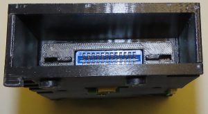
The size of the frame, and the placement of the buttons were dictated by the size of the Atari 2600 cartridge. I designed it to have just over an inch of the cartridge exposed when it is fully inserted. This was done to allow it to be easily removed, but still look good by not having too much of the cartridge hanging out. The buttons were then placed so that the PLAY and STOP buttons could be easily pressed with my left thumb while holding the device in my left hand.
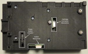
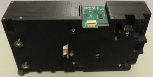
The main circuit board attaches to the bottom of the frame, and there are two mezzanine circuit boards as well. The cartridge connector mezzanine attaches to the back face of the cartridge slot, and brings the cartridge address and data buses down to the main board through a 30 pin JMD connector.
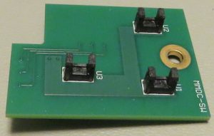
The switch mezzanine holds three photocouplers used for the GAME SELECT, GAME RESET, and PAUSE buttons. When one of these buttons is pressed, the button shaft extends into the photocoupler, and breaks the light beam. The signals from the photocouplers are buffered and shaped through a Schmitt inverter before being sent to the main circuit board through a 30 pin JMD connector.
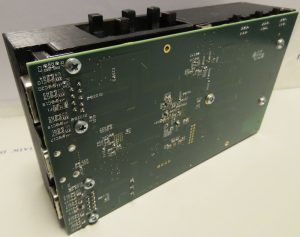
At the heart of all this is the main circuit board. It is a six layer PCB that contains the FPGA, the HDMI transmitter, and all of the various support chips and components. I designed this board specifically for an Atari 2600 system, but since then I have been able to configure the FPGA for C64 and Pacman coin-op systems as well. Looking back I should have made the board design more flexible so that it could support all of the 8-bit systems, but hindsight is always twenty-twenty, isn’t it?
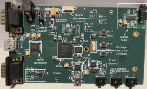
Specific to the Atari 2600 is the support hardware for paddles. The Atari TIA chip has internal Schmitt triggers on its paddle inputs that make up part of the circuit used to detect the paddle position. Unfortunately, Xilinx doesn’t provide any kind of hysteresis options in its FPGA IO, so I had to do it myself. The circuit uses a 74LVC14A Schmitt inverter, which is a 3.3 volt part with 5 volt tolerant inputs, and it provides paddle position detection as well as level translation.
The analog audio hardware is also specific to the Atari 2600. I would like to expand the board design to include all of the SID sound chip analog circuitry. With something like that in place, I could do a C64 system with perfect sound.
One other point of interest is the power supply for the USB bridge chip and FLASH memory. The circuit is designed so that when the board is not powered from the wall wart, the USB bridge chip and FLASH memory get power from the USB cable. This arrangement allows me re-flash the console at my computer without having to bring the wall wart along for power.
As for the rest of the design, it’s all just point to point wiring between the FPGA and the various chips. The level translators for the joystick ports are bidirectional, so that the system will work with input devices as well as peripherals such as the AtariVox.
I want one!!!
Great Work
Could i buy one of these? my 8 year old and I would have a blast on this.
I got a lot of Atari 2600 cartridges collecting dust with no way to play them, and this would be perfect! Do you have any plans for making your device available to the public?
I would still want to buy this over the Retron 77. Would you be interested in making more of them?
I would love to produce and sell these, but I currently don’t have a way of manufacturing them for a reasonable cost. It’s unlikely that anyone would be willing to spend $799 for one of these.
I’ve been working on other projects lately, and sad to say neglecting this one. However, I haven’t completely given up on it. I met a couple of people at the AmiWest show over the weekend who may be able to help in getting the cost of manufacture down. If we come up with something, I’ll be sure to post news about it here.